Hardware Overview
Overview
The SparkX Satellite Transceiver Function Board - Swarm M138 is quite a simple board. The following is a summary of its features and functions:
Power- Power for the Swarm M138 modem is drawn from the MicroMod VCC pins- The modem requires 3.0VMin, 5.0VMax
- VCC will be 5.0V when the MicroMod Main Board is powered via USB-C
- VCC will be between 3.6V and 4.2V when the MicroMod Main Board is drawing power from a LiPo battery
High-Side Power Switch- Power for the Swarm M138 modem is connected via a MIC94064 High-Side Power Switch- By default, the modem power is turned off
- Modem power can be enabled by pulling the PWR_EN pin high
- PWR_EN is connected to the MicroMod Processor - the exact pin depends on which Main Board and Processor Board are being used. See the table below for example pins
- Modem power can be disabled by pulling the PWR_EN pin low or leaving it unconnected
- The EN split pad jumper can be soldered closed to permanently enable modem power
TX and RX- The M138 modem uses 3.3V serial (UART) to communicate at 115200 baud (8 data bits, 1 stop bit, no parity)- TXO and RXI are connected to UART pins on the MicroMod Processor
GPIO1- The modem's GPIO1 pin can perform several functions- GPIO1 is connected to a GPIO pin on the MicroMod Processor - the exact pin depends on which Main Board and Processor Board are being used. See the table below for example pins
- GPIO1 can be configured as a "wake from sleep mode" input
- GPIO1 can be configured as a "unread messages", "unsent messages" or "sleep mode active" output
- When configured as an output, GPIO1 is "open drain". A configurable pull-up resistor provides the high logic level
TX/RX- The modem's TX/RX pin indicates if the modem is transmitting or receiving- TX/RX is connected to a GPIO pin on the MicroMod Processor - the exact pin depends on which Main Board and Processor Board are being used. See the table below for example pins
- TX/RX is high when the modem is transmitting, low when receiving
EEPROM- Like all MicroMod Function Boards, a small EEPROM is provided- The Processor Board can read the EEPROM to discover which Function Boards are connected
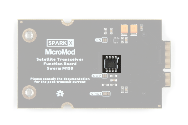
Board Images
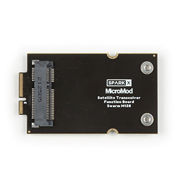
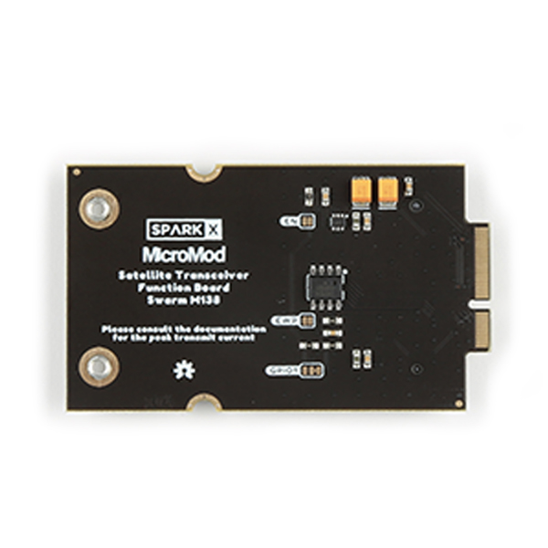
Board images. (Click to enlarge)
Board Dimensions
The board dimensions are illustrated in the drawing below. The listed measurements are in mm. The two mounting holes and two stand-offs are compatible with M2.5 screws.
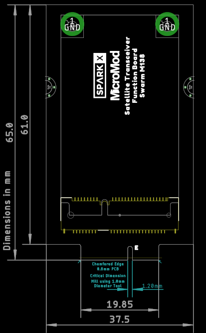
Board dimensions. (Click to enlarge)
M.2 Connector Pinout
The pinout of the function board's M.2 edge connector (gold fingers) is defined in the following table.
Note that the M.2 connector pins on opposing sides are offset from each other as indicated by the bottom pins where it says "(Not Connected)".
There is no connection to pins that have a "-" under the primary function.
| Function |
Bottom Pin |
Top Pin |
Function | ||
|---|---|---|---|---|---|
| (Not Connected) |
75 | GND | |||
| VCC | 74 | 73 | 3.3V | ||
| VCC | 72 | 71 | PWR_EN | Power Enable Pull high to enable power |
|
| - | 70 | 69 | - | ||
| - | 68 | 67 | - | ||
| - | 66 | 65 | - | ||
| - | 64 | 63 | - | ||
| - | 62 | 61 | - | ||
| - | 60 | 59 | - | ||
| - | 58 | 57 | - | ||
| - | 56 | 55 | - | ||
| - | 54 | 53 | TX/RX | Modem State Transmit (High) Receive (Low) |
|
| - | 52 | 51 | - | ||
| - | 50 | 49 | - | ||
| - | 48 | 47 | GPIO1 | Modem GPIO1 I/O pin |
|
| - | 46 | 45 | GND | ||
| - | 44 | 43 | - | ||
| - | 42 | 41 | - | ||
| Write Protect | EEPROM WP | 40 | 39 | GND | |
| - | 38 | 37 | - | ||
| EEPROM A0 | 36 | 35 | - | ||
| EEPROM A1 | 34 | 33 | GND | ||
| EEPROM A2 | 32 | 31 | Module Key | ||
| Module Key | 30 | 29 | Module Key | ||
| Module Key | 28 | 27 | Module Key | ||
| Module Key | 26 | 25 | Module Key | ||
| Module Key | 24 | 23 | - | ||
| - | 22 | 21 | EEPROM SCL | ||
| - | 20 | 19 | EEPROM SDA | ||
| - | 18 | 17 | - | ||
| - | 16 | 15 | RXI | Modem UART In | |
| - | 14 | 13 | TXO | Modem UART Out | |
| - | 12 | 11 | - | ||
| - | 10 | 9 | - | ||
| GND | 8 | 7 | - | ||
| - | 6 | 5 | - | ||
| - | 4 | 3 | - | ||
| GND | 2 | 1 | GND | ||
For more details, users can reference the schematic.
Example Pin Connection Table
The pin connections depend on which MicroMod Main Board and Processor Board are being used.
The table below provides an example for the Artemis Processor Board and the Main Board - Double.
|
Satellite Function Board Pin Name |
Processor I/O Direction |
Main Board's Processor Pin |
|
|---|---|---|---|
| Slot 0 | Slot 1 | ||
| VCC | Power | VCC | VCC |
| GND | Power | GND | GND |
| PWR_EN | O | PWR_EN0 (SDIO_DATA2) |
PWR_EN1 (SDIO_DATA1) |
| TXO | I | RX1 | RX2 |
| RXI | O | TX1 | TX2 |
| GPIO1 | I/O | D0 | D1 |
| TX/RX | I | G0 | G5 |
Power Control (High-Side Power Switch)
Power for the Swarm M138 modem is drawn from the MicroMod VCC pins. The modem requires 3.0VMin, 5.0VMax.
VCC will be 5.0V when the MicroMod Main Board is powered via USB-C, and between 3.6V and 4.2V when the MicroMod Main Board is drawing power from a LiPo battery.
Power for the Swarm M138 modem is connected via a MIC94064 High-Side Power Switch.
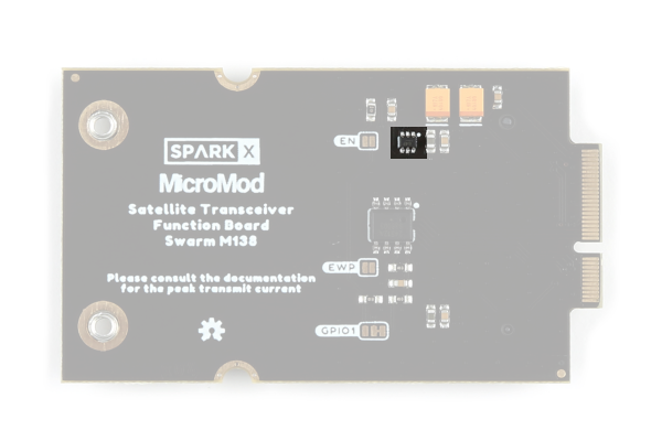
The high-side power switch. (Click to enlarge)
Modem power can be disabled by pulling the PWR_EN pin low or leaving it unconnected. By default, the modem power is turned off.
Modem power can be enabled by pulling the PWR_EN pin high. PWR_EN is connected to the MicroMod Processor - the exact pin depends on which Main Board and Processor Board are being used. See the table above for example pins.
If required, the EN split pad jumper can be soldered closed to permanently enable modem power.
Current Consumption
The modem's average current draw and peak draw during transmit depend on the supply voltage VCC. For more details, please consult the Satellite Transceiver Breakout - Swarm M138 - Hookup Guide.
When the PWR_EN pin is pulled low, the modem is powered off completely. The MIC94064 has a very low quiescent current of 2µA.
EEPROM
Like all MicroMod Function Boards, the board includes a small serial (I2C) EEPROM. This can be programmed with a 'signature' to allow the Processor Board to detect which boards are installed.
The EEPROM. (Click to enlarge)
By default, the EEPROM is write protected. The WP pin is pulled up by a 100K resistor. Soldering the EWP jumper closed will pull WP low, disabling write protection.
Jumpers
Note
Never modified a jumper before? Check out our Jumper Pads and PCB Traces tutorial for a quick introduction!

There are three jumpers on the back of the board that can be used to modify how the board functions.
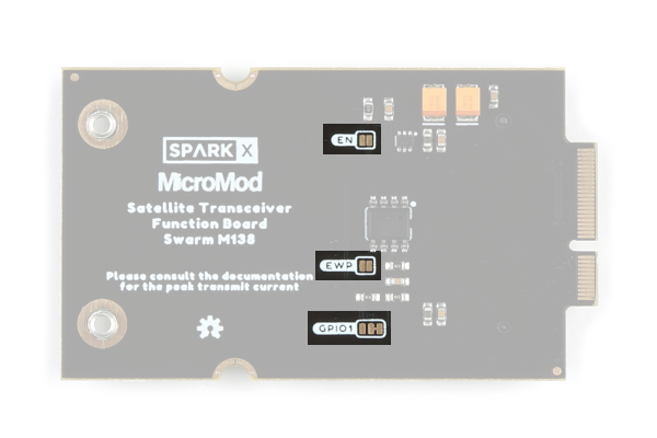
The jumpers on the back of the function board. (Click to enlarge)
- GPIO1 - This is a double-jumper which connects pull-up and/or pull-down resistors to the modem's GPIO1 pin.
- By default, the 100K pull-up resistor is connected so that a logic high is output when GPIO1 is in one of its "open drain" output modes
- The pull-up can be disconnected by opening the closed half of the jumper
- A 100K pull-down can be connected by closing the open half of the jumper
- Both pull-up and pull-down can be connected to bias GPIO1 with 1.65V when it is configured as an analog input
- EN - This jumper can be closed to connect a 100K pull-up resistor to the high-side power switch's enable pin (PWR_EN)
- Closing the jumper will cause the modem to be powered continuously
- Some MicroMod Processor Boards do not have a GPIO pin connected to PWR_EN. If you are using one of these boards, solder the EN jumper closed to power the modem
- EWP - This jumper can be closed to disable the EEPROM write protection
- By default, the EEPROM is write protected. The WP pin is pulled up by a 100K resistor
- Soldering the EWP jumper closed will pull WP low, disabling write protection