Hardware Assembly
Step 1: Mount the SparkX Satellite Transceiver Function Board
To begin, the SparkX Satellite Transceiver Function Board needs to be mounted on your chosen MicroMod main board. It is designed to be plugged into the MicroMod Main Board - Single or MicroMod Main Board - Double.
Note
If you have not already, make sure to check out the Getting Started with MicroMod: Hardware Hookup for information on inserting your Processor and Function Boards to the Main Board.
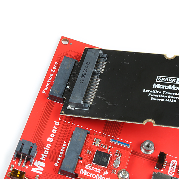
Insert the function board at an angle into the M.2 connector. The board will stick up at an angle (at around 25°).
Inserting the function board. (Click to enlarge)
Hold down the board, insert the screws, and start to tighten. Once the screws make contact with the circuit board, tighten each one just a little and then swap to the other. By swapping between the two screws and tightening each one a little at a time, you can prevent the function board from 'walking' out of alignment.
Attention
If you are unable to power up your M138 modem and communicate with it, it may be because the M.2 contacts (gold fingers) are slightly out of alignment. Remove the screws, remove the function board, re-insert it while pushing it gently over to one side, and replace the screws. If you are still unable to communicate with the modem, repeat the process and gently push to the other side as you re-insert the board. Tighten both screws a little at a time to prevent the board from 'walking' out of alignment.
Inserting the function board. (Click to enlarge)
Step 2: Mount the Swarm M138 Modem
Now it is time to insert and secure the M138 modem.
Insert the modem at an angle into the M.2 connector. The modem will stick up at an angle (at around 25°).
Inserting the modem. (Click to enlarge)
Hold down the modem, insert the screws, and start to tighten. Once the screws make contact with the circuit board, tighten each one just a little and then swap to the other. By swapping between the two and tightening each one a little at a time, you can prevent the modem from 'walking' out of alignment.
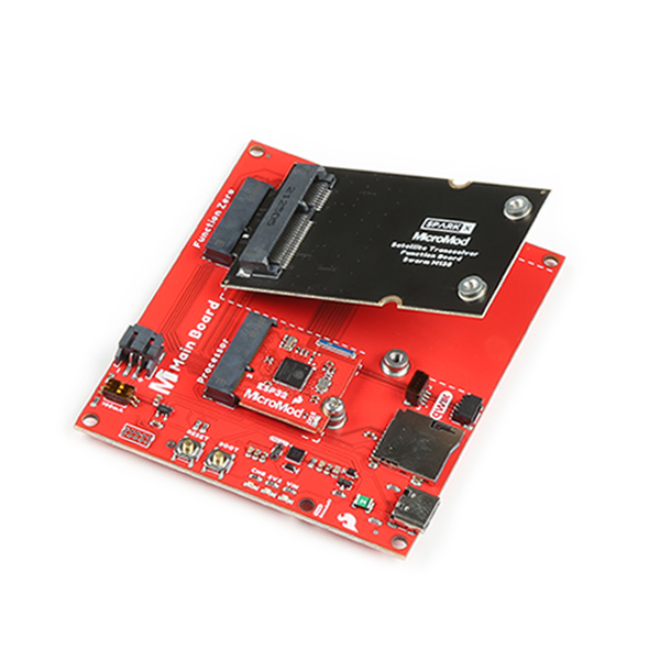
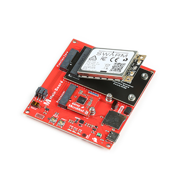
After securing the modem, your setup should look like the image below.
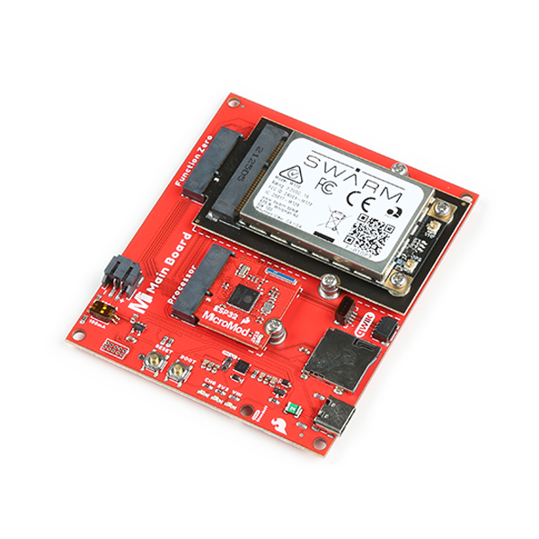
The function board and modem, assembled. (Click to enlarge)
Step 3: Attach the two u.FL antenna connections
The M138 modem requires two antennas: one for VHF (to communicate with the Swarm satellites) and a separate one for GPS (GNSS, for satellite location). Both are connected via u.FL.
Go ahead and attach both antenna connections. For your MicroMod project, you may find it useful to use u.FL-to-SMA adapter cables. SMA connectors are much more robust than u.FL and can be mounted on your project enclosure ("bulkhead" connections).
Note
If you have not already, make sure to check out our Three Quick Tips About Using U.FL tutorial for information on disconnecting and reconnecting the antenna connections.